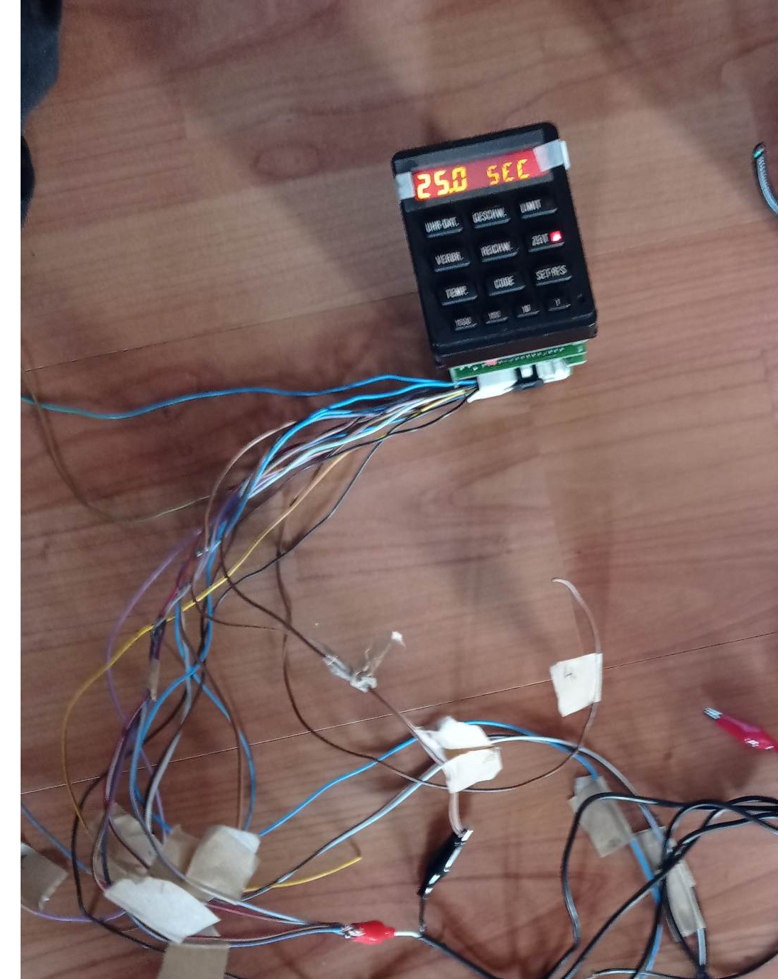
So here are the pinouts on OBC2
Green plug on OBC2
1 Br/Yl (really Br) Horn(-) Relay coil control, power to OBC horn
2 Br/Bu trigger output (cold chime)
3 N/C
4 Bk-- Combination switch (turn signal stalk), momentary contact to ground
5 GyVl KLR C3-13, hot in accy/run/start fuse 12
6 Rd/Wt KL30, hot at all times, power from fuse 21 through cluster+SI board
7 Gn/Bk (really Gn/Wt) KL15 C3-2, hot in run/start through fuse 10
8 Gy/Rd dash lights
9 Br/Wt "31G" Br/Wt dash lights, variable resistor to ground.
10 Br "31" Ground through cluster
11 Br/Bu (really Br/Gn) Code(-) Relay coil control for Motronic power
12,13 N/C
14 Yl not used (Euro "alarm clock" feature")
15 Br/Gn fuel tank level input, through cluster C3-5 [!!Br/Yl actual color code!!]
16 Bu outside temp input, NTC thermistor to ground [!!Bu/Yl actual color!!]
17 Wt/Bu fuel rate input, C3-25, fuel injector pulse width info from Motronic
18 Br/Gy fuel tank low level input, through cluster C3-4, ground w/ low fuel [!!Br/Bk actual color!!]
19 N/C
20 N/C
21 Br/Rd speed input, C3-26, same as signal to cruise control
22 Bk/Yl start input, hot in start
23,24,25,26 N/C
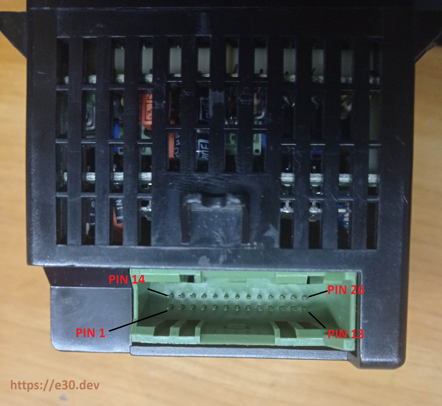
Yellow plug on instrument cluster
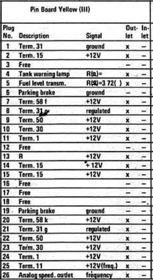
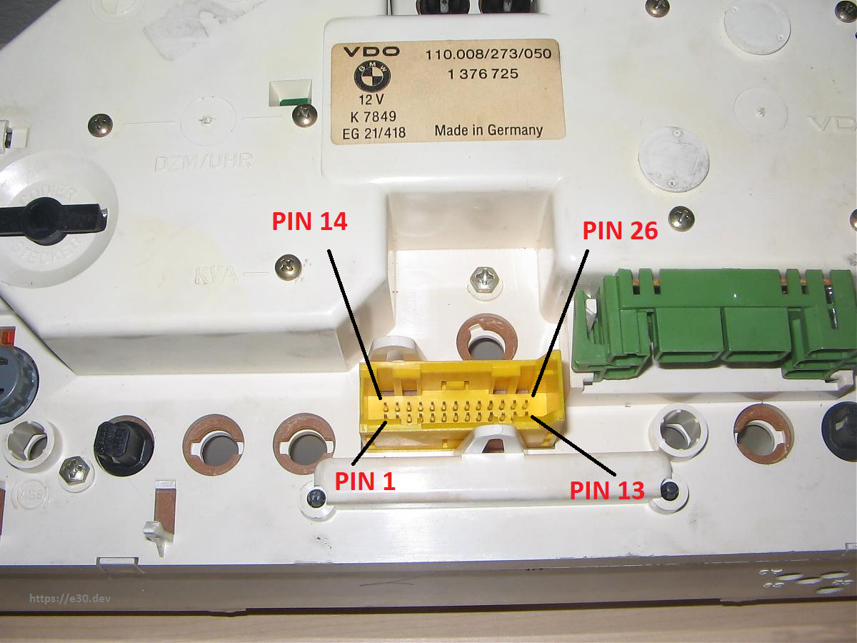
If you want to test out OBC2 outside car - here are pins you should use:
PIN 5 on obc2 (+12v)
PIN 6 on obc2 (+12v)
PIN 7 on obc2 (+12v)
PIN 8 on obc2 (+12v)
PIN 9 on obc2 (ground)
PIN 10 on obc2 (ground)
(if you want to simulate turn signal stalk BC switch - you can momentary contact PIN 4 (on obc2) to ground.)
Example:
